EVKB-IMXRT1050_MDK
Rev. A1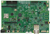
-
Core
Cortex-M7
-
Debug interface
JTAG/SW
-
Device
MIMXRT1052DVL6B -
CMSIS Pack
IMXRT1050-EVKB_BSP
NXP IMXRT1050-EVKB
Overview
The i.MX RT1050 EVK is a 4-layer through-hole USB-powered PCB. At its heart lies the i.MX RT1050 crossover MCU, featuring NXP's advanced implementation of the Arm Cortex-M7 core. This core operates at speeds up to 600 MHz to provide high CPU performance and great real-time response.
Schematics
Power supply
A DC 5V external power supply is used to supply the board at J2, and a slide switch SW1 is used to turn the Power ON/OFF. J28 and J9 also can be used to supply the EVK Board. Different power supply need to configure different Jumper setting of J1:
| Power supply | J1 setting |
|---|---|
| J2 | 1-2 |
| J9 | 3-4 |
| J28 | 5-6 |
Note
If you do not have an external DC 5 V power supply, it is recommended to supply the board via J9 with a standard 5 V USB power supply. Supplying the board via J28 (which is connected to the on-board CMSIS-DAP debug adapter) is not recommended when using Arduino shields or Ethernet.
CMSIS-Drivers
This board support pack contains a CMSIS-Driver for the VIO interface. This is a virtual I/O abstraction for peripherals that are typically used in example projects. The Blinky example uses this interface to create a blinking light with the USER LED mounted on the board that can be controlled by the USER BUTTON (SW8).
| Virtual Resource | Variable | Physical Resource on IMXRT1050-EVKB |
|---|---|---|
| vioBUTTON0 | vioSignalIn.0 | WAKEUP SW8(USER_BUTTON) |
| vioLED0 | vioSignalOut.0 | GPIO_AD_B0_09 (USER_LED) |
| vioMotionAccelero | vioValueXYZ[1] | 3-Axis Accelerometer (FXOS8700CQ) |
| vioMotionMagneto | vioValueXYZ[2] | 3-Axis Magnetometer (FXOS8700CQ) |
Refer to the schematics for board connection information.
WiFi Shields
For the correct operation of WiFi shields using the Arduino R3 header, make sure that the following jumpers are correctly fitted:
| Jumper | Setting |
|---|---|
| J26 | closed |
| J27 | 1-2 |
Special considerations
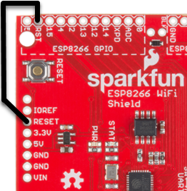
For correct operation, the SparkFun ESP8266 WiFi Shield requires a jumper cable to connect the RESET pin on the Arduino connector with the RST pin in the area marked as ESP8266 GPIO:
For stable operation, make sure that you are using an external DC 5V power supply (connected to J2). Also, fit jumper J1 to 1-2 closed and set the switch SW1 to position 2-3.
CMSIS-DAP Firmware
Make sure that you have updated your CMSIS-DAP firmware to the latest version. This makes the board compatible with Keil Studio Cloud that enables browser-based project creation and debugging. The following instructions apply if your board is equipped with at U23 a Kinetis K20DX device (marked as M20AGV).
Using HyperFlash
If your board is configured for HyperFlash (SW7 is set to OFF/ON/ON/OFF), use the following CMSIS-DAP firmware: DAPLink 0254
Using QSPI Flash
If your board is configured for QSPI Flash (SW7 is not set to OFF/ON/ON/OFF), use the following CMSIS-DAP firmware: DAPLink 0254
Jumper settings
Close 1-2 on jumper block J27 (top right corner of the board).
Flashing instructions for Windows users
- While holding down the SW4 button, connect the board's USB debug port (J28) to the computer. It should enumerate and mount as MAINTENANCE.
- Drag-and-drop the firmware file onto the mounted drive.
- Wait for the file copy operation to complete.
- Power cycle the board. It will now enumerate and mount as RT1050-EVK.
Flashing instructions for MAC users
- While holding down the SW4 button, connect the board's USB debug port (J28) to the computer. It should enumerate as MAINTENANCE.
- In a terminal execute
sudo mount -u -w -o sync /Volumes/MAINTENANCE ; cp -X <path to firmware file> /Volumes/MAINTENANCE/
Note: If your drive does not mount as MAINTENANCE make sure to change this to match the name of the mounted disk attached to your system. - Wait for the file copy operation to complete.
- Power cycle the board. It will now enumerate and mount as RT1050-EVK.
Flashing instructions for Linux users
- While holding down the SW4 button, connect the board's USB debug port (J28) to the computer. It should enumerate as MAINTENANCE.
- In a terminal execute
$ cp <path to firmware file> <MAINTENANCE> && sync
Note: make sure to change MAINTENANCE to the name of the mount point of the drive on your system. - Power cycle the board. It will now enumerate and mount as RT1050-EVK.
Accessing the board in Keil Studio under Linux
- On Linux, permission to access USB devices from user space must be explicitly granted via udev rules. This repo contains daplink.rules that you can copy to make this work.
- To install, copy the daplink.rules to
/etc/udev/rules.d/on Ubuntu:
$ sudo cp daplink.rules /etc/udev/rules.d - To see your changes without a reboot, you can force the udev system to reload:
$ sudo udevadm control --reload
$ sudo udevadm trigger