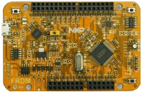
FRDM-KV11Z
-
Core
Cortex-M0+
-
Device
MKV11Z128VLH7 -
CMSIS Pack
FRDM-KV11Z_BSP
-
edma_ping_pong_transfer
-
 Download .zip
- Try it out Requires conversion
-
 Open in Keil Studio
Keil Studio, µVision AC6The EDMA memory to memory example is a simple demonstration program that uses the SDK software.It excuates one shot transfer from source buffer to destination buffer using the SDK EDMA drivers.The purpose of this example is to show how to use the EDMA and to provide a simple example fordebugging and further development.
Download Pack -
-
edma_scatter_gather
-
Download .zip
- Try it out Requires conversion
-
Open in Keil Studio
Keil Studio, µVision AC6The EDMA memory to memory example is a simple demonstration program that uses the SDK software.It excuates one shot transfer from source buffer to destination buffer using the SDK EDMA drivers.The purpose of this example is to show how to use the EDMA and to provide a simple example fordebugging and further development.
Download Pack -
-
edma_wrap_transfer
-
Download .zip
- Try it out Requires conversion
-
Open in Keil Studio
Keil Studio, µVision AC6The EDMA memory to memory example is a simple demonstration program that uses the SDK software.It excuates one shot transfer from source buffer to destination buffer using the SDK EDMA drivers.The purpose of this example is to show how to use the EDMA and to provide a simple example fordebugging and further development.
Download Pack -
-
ewm
-
Download .zip
- Try it out Requires conversion
-
Open in Keil Studio
Keil Studio, µVision AC6The EWM Example project is to demonstrate usage of the KSDK EWM driver.In the example, EWM counter is continuously refreshed until button is pressed.Once the button is pressed, EWM counter will expire and interrupt will be generated.After the first pressing, another interrupt can be triggered by pressing button again.
Download Pack -
-
flexcan_interrupt_transfer
µVision AC6The flexcan_interrupt example shows how to use FlexCAN driver in none-blocking interrupt way:In this example, 2 boards are connected through CAN bus. Endpoint A(board A) send a CAN Message toEndpoint B(board B) when user press space key in terminal. Endpoint B receive the message, printthe message content to terminal and echo back the message. Endpoint A will increase the receivedmessage and waiting for the next transmission of the user initiated.
Download Pack -
flexcan_loopback
-
Download .zip
- Try it out Requires conversion
-
Open in Keil Studio
Keil Studio, µVision AC6The flexcan_loopback_functional example shows how to use the loopback test mode to debug your CAN Bus design:To demonstrates this example, only one board is needed. The example will config one FlexCAN MessageBuffer to Rx Message Buffer and the other FlexCAN Message Buffer to Tx Message Buffer with same ID.After that, the example will send a CAN Message from the Tx Message Buffer to the Rx Message Bufferthrouth internal loopback interconnect and print out the Message payload to terminal.
Download Pack -
-
flexcan_loopback_edma_transfer
µVision AC6The flexcan_loopback_edma example shows how to use the EDMA version transactional driver to receiveCAN Message from Rx FIFO:To demonstrates this example, only one board is needed. The example will config one FlexCAN MessageBuffer to Tx Message Buffer and also setup Rx FIFO. After that, the example will send 4 CAN Messagesfrom Tx Message Buffer to Rx FIFO through internal loopback interconnect and read them out usingEDMA version FlexCAN transactional driver. The Sent and received message will be print out to terminalat last.
Download Pack -
flexcan_loopback_transfer
µVision AC6The flexcan_loopback example shows how to use the loopback test mode to debug your CAN Bus design:To demonstrates this example, only one board is needed. The example will config one FlexCAN MessageBuffer to Rx Message Buffer and the other FlexCAN Message Buffer to Tx Message Buffer with same ID.After that, the example will send a CAN Message from the Tx Message Buffer to the Rx Message Bufferthrough internal loopback interconnect and print out the Message payload to terminal.
Download Pack -
ftm_combine_pwm
-
Download .zip
- Try it out Requires conversion
-
Open in Keil Studio
Keil Studio, µVision AC6The FTM project is a demonstration program of generating a combined PWM signal by the SDK FTM driver. It sets up the FTMhardware block to output PWM signals on two TPM channels. The example also shows the complementary mode of operationand deadtime insertion.On boards that have 2 LEDs connected to the FTM pins, the user will see a change in LED brightness.And if the board do not support LEDs to show, the outputs can be observed by oscilloscope.
Download Pack -
-
ftm_dual_edge_capture
-
Download .zip
- Try it out Requires conversion
-
Open in Keil Studio
Keil Studio, µVision AC6The FTM project is a demonstration program of the SDK FTM driver's dual-edge capture feature.This feature is available only on certain SoC's.The example sets up a FTM channel-pair for dual-edge capture. Once the input signal is received,this example will print the capture values and period of the input signal on the terminal window.
Download Pack -