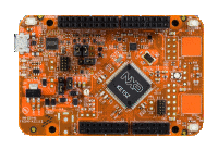
FRDM-KE15Z
-
Core
Cortex-M0+
-
Device
MKE15Z256VLL7 -
CMSIS Pack
FRDM-KE15Z_BSP
-
lpuart_polling
µVision AC6The lpuart_polling Example project is to demonstrate usage of the KSDK lpuart driver.In the example, you can send characters to the console back and they will be printed out onto console instantly.
Download Pack -
lpuart_polling
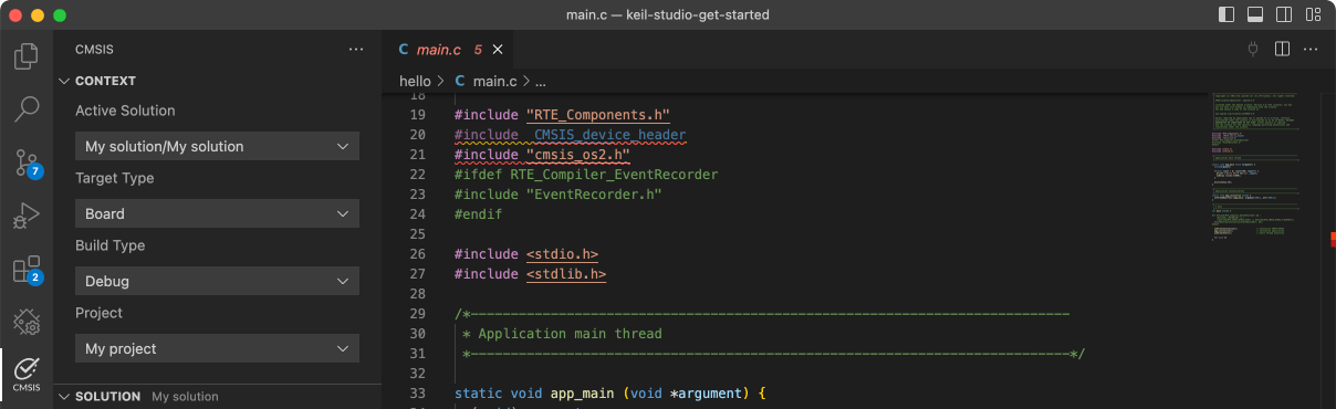
Keil Studio AC6, GCC, IARThe lpuart_polling Example project is to demonstrate usage of the KSDK lpuart driver.In the example, you can send characters to the console back and they will be printed out onto console instantly.
Download Pack -
lpuart_polling_seven_bits
Keil Studio AC6, GCC, IARThe lpuart_polling_seven_bits Example project is to demonstrate usage of the KSDK lpuart driver with seven data bits feature enabled.In the example, you can send characters to the console back and they will be...See more details in readme document.
Download Pack -
lpuart_polling_seven_bits
µVision AC6The lpuart_polling_seven_bits Example project is to demonstrate usage of the KSDK lpuart driver with seven data bits feature enabled.In the example, you can send characters to the console back and they will be...See more details in readme document.
Download Pack -
mmdvsq
Keil Studio AC6, GCC, IARThe MMDVSQ Example project is a demonstration program that uses the KSDK software to Calculation square root and QuotientMMDVSQ Peripheral Driver ExampleStart MMDVSQ ExampleCalculation square root, please enter...See more details in readme document.
Download Pack -
mmdvsq
µVision AC6The MMDVSQ Example project is a demonstration program that uses the KSDK software to Calculation square root and QuotientMMDVSQ Peripheral Driver ExampleStart MMDVSQ ExampleCalculation square root, please enter...See more details in readme document.
Download Pack -
new_project
Keil Studio AC6, GCC, IARThe new project is provided as starting point for user to add with customized flow.
Download Pack -
new_project
µVision AC6The new project is provided as starting point for user to add with customized flow.
Download Pack -
pdb_adc12_trigger
µVision AC6The pdb_adc12_trigger example shows how to use the PDB to generate a ADC trigger.Based on the basic counter, to use the ADC trigger, just to enable the ADC trigger's "milestone" and set the user-defined value for...See more details in readme document.
Download Pack -
pdb_adc12_trigger
Keil Studio AC6, GCC, IARThe pdb_adc12_trigger example shows how to use the PDB to generate a ADC trigger.Based on the basic counter, to use the ADC trigger, just to enable the ADC trigger's "milestone" and set the user-defined value for...See more details in readme document.
Download Pack