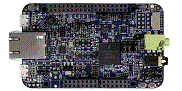
FRDM-K66F
-
Core
Cortex-M4
-
Device
MK66FN2M0xxx18
-
CMSIS Pack
FRDM-K66F_BSP
-
pdb_dac_trigger
-
 Download .zip
- Try it out Requires conversion
-
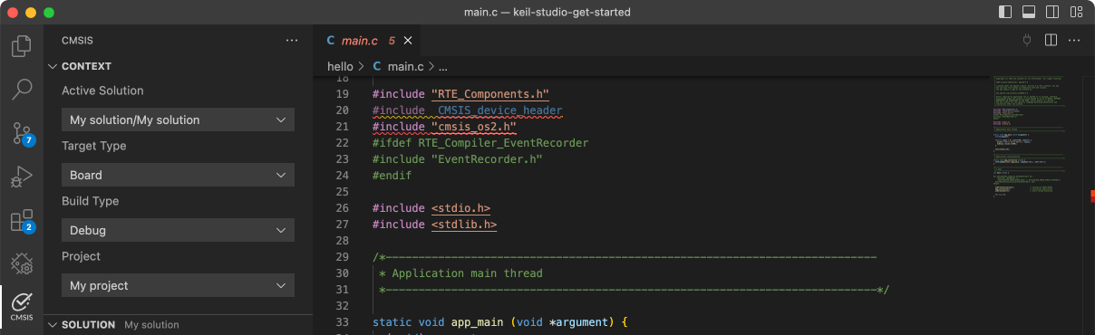
 Open in Keil Studio
Keil Studio, µVision AC6The pdb_dac_trigger example shows how to use the PDB to generate a DAC trigger.Based on the basic counter, to use the DAC trigger, just to enable the DAC trigger's "milestone" and set the user-defined value for it.The DAC's "milestone" is called as "interval". Multiple DAC trigger intervals can be included into one PDB counter's cycle.DAC trigger's counter would reset after the trigger is created and start counting again to the interval value.In this example, the DAC is configured with hardware buffer enabled in normal work mode. Once it gets the trigger from the PDB, the buffer read pointer increases.
Download Pack -
-
pdb_delay_interrupt
-
Download .zip
- Try it out Requires conversion
-
Open in Keil Studio
Keil Studio, µVision AC6The pdb_delay_interrupt example show how to use the PDB as a general programmable interrupt timer.The PDB is triggered by software, and other external triggers are generated from PDB in this project,so that user can see just a general counter is working with interrupt.
Download Pack -
-
pflash
-
Download .zip
- Try it out Requires conversion
-
Open in Keil Studio
Keil Studio, µVision AC6The pflash example shows how to use flash driver to operate program flash:
Download Pack -
-
pit
-
Download .zip
- Try it out Requires conversion
-
Open in Keil Studio
Keil Studio, µVision AC6The PIT project is a simple demonstration program of the SDK PIT driver. It sets up the PIThardware block to trigger a periodic interrupt after every 1 second. When the PIT interrupt is triggereda message a printed on the UART terminal and an LED is toggled on the board.
Download Pack -
-
power_manager
-
Download .zip
- Try it out Requires conversion
-
Open in Keil Studio
Keil Studio, µVision AC6The Power manager demo application demonstrates the use of power modes in the KSDK. The demo use the notification mechanismand prints the power mode menu through the debug console, where the user can set the MCU to a specific power mode. The usercan also set the wakeup source by following the debug console prompts. The purpose of this demo is to demonstrate theimplementation of a power mode manager. The callback can be registered to the framework. If a power mode transition happens,the callback will be called and user can do something. Tips: This demo is to show how the various power mode can switch to each other. However, in actual low power use case, to save energy and reduce the consumption even more, many things can be done including: - Disable the clock for unnecessary module during low power mode. That means, programmer can disable the clocks before entering the low power mode and re-enable them after exiting the low power mode when necessary. - Disable the function for unnecessary part of a module when other part would keep working in low power mode. At the most time, more powerful function means more power consumption. For example, disable the digital function for the unnecessary pin mux, and so on. - Set the proper pin state (direction and logic level) according to the actual application hardware. Otherwise, the pin cirrent would be activied unexpectedly waste some energy. - Other low power consideration based on the actual application hardware.
Download Pack -
-
power_mode_switch
-
Download .zip
- Try it out Requires conversion
-
Open in Keil Studio
Keil Studio, µVision AC6The Power mode switch demo application demonstrates the use of power modes in the KSDK. The demo prints the power mode menuthrough the debug console, where the user can set the MCU to a specific power mode. The user can also set the wakeupsource by following the debug console prompts. The purpose of this demo is to show how to switch between different power modes, and how to configure a wakeup source and wakeup the MCU from low power modes. Tips: This demo is to show how the various power mode can switch to each other. However, in actual low power use case, to save energy and reduce the consumption even more, many things can be done including: - Disable the clock for unnecessary module during low power mode. That means, programmer can disable the clocks before entering the low power mode and re-enable them after exiting the low power mode when necessary. - Disable the function for unnecessary part of a module when other part would keep working in low power mode. At the most time, more powerful function means more power consumption. For example, disable the digital function for the unnecessary pin mux, and so on. - Set the proper pin state (direction and logic level) according to the actual application hardware. Otherwise, the pin cirrent would be activied unexpectedly waste some energy. - Other low power consideration based on the actual application hardware. - Debug pins(e.g SWD_DIO) would consume addtional power, had better to disable related pins or disconnect them.
Download Pack -
-
rnga_random
-
Download .zip
- Try it out Requires conversion
-
Open in Keil Studio
Keil Studio, µVision AC6The RNGA is a digital integrated circuit capable of generating the 32-bit random numbers. The RNGAExample project is a demonstration program that uses the KSDK software to generate random numbersand prints them to the terminal.
Download Pack -
-
rtc
-
Download .zip
- Try it out Requires conversion
-
Open in Keil Studio
Keil Studio, µVision AC6The RTC project is a simple demonstration program of the SDK RTC driver. It sets up the RTChardware block to trigger an alarm after a user specified time period. The test will set the currentdate and time to a predefined value. The alarm will be set with reference to this predefined dateand time.
Download Pack -
-
rtc_func
-
Download .zip
- Try it out Requires conversion
-
Open in Keil Studio
Keil Studio, µVision AC6The RTC demo application demonstrates the important features of the RTC Module by using the RTC Peripheral Driver.The RTC demo supports the following features:- Calendar + Get the current date time with Year, Month, Day, Hour, Minute, and Second. + Set the current date time with Year, Month, Day, Hour, Minute, and Second.- Alarm + Set the alarm based on the current time. + Application prints a notification when the alarm expires.- Seconds interrupt + Use second interrupt function to display a digital time blink every second.
Download Pack -
-
rtc_func_peripheral
-
Download .zip
- Try it out Requires conversion
-
Open in Keil Studio
Keil Studio, µVision AC6The RTC demo application demonstrates the important features of the RTC Module by using the RTC Peripheral Driver.The RTC demo supports the following features:- Calendar + Get the current date time with Year, Month, Day, Hour, Minute, and Second. + Set the current date time with Year, Month, Day, Hour, Minute, and Second.- Alarm + Set the alarm based on the current time. + Application prints a notification when the alarm expires.- Seconds interrupt + Use second interrupt function to display a digital time blink every second.
Download Pack -