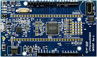
1. Boards
  2. LPCXpresso845MAX

LPCXpresso845MAX

NXP
LPCXpresso845MAX
VSCode with the Arm Keil Studio extension

Accelerate your application development with example projects

Import your chosen project to Keil Studio for VS Code or Keil Studio Cloud, or download for use in Keil uVision.

Learn more about Keil tools
  • Keil Studio AC6, GCC, IAR

    The lpc_adc_dma example shows how to use LPC ADC driver with DMA.In this example, the internal temperature sensor is used to created the input analog signal. When user type in any key from the keyboard, the software trigger API is called to start the conversion. When the ADC conversion is completed, it would trigger the DMA to move the ADC conversion result from ADC conversion data register to user indicated memory. Then the main loop waits for the transfer to be done and print the result to terminal.Project Information1.what are ADC conversion sequences? A conversion sequence is a single pass through a series of A/D conversions performed on a selected set of A/D channels. Software can set-up two independent conversion sequences, either of which can be triggered by software or by a transition on one of the hardware triggers. Each sequence can be triggered by a different hardware trigger. One of these conversion sequences is referred to as the A sequence and the other as the B sequence. It is not necessary to employ both sequences. An optional single-step mode allows advancing through the channels of a sequence one at a time on each successive occurrence of a trigger. The user can select whether a trigger on the B sequence can interrupt an already-in-progress A sequence. The B sequence, however, can never be interrupted by an A trigger. 2. How to use software-triggered conversion? There are two ways that software can trigger a conversion sequence: 1. Start Bit: The first way to software-trigger an sequence is by setting the START bit in the corresponding SEQn_CTRL register. The response to this is identical to occurrence of a hardware trigger on that sequence. Specifically, one cycle of conversions through that conversion sequence will be immediately triggered except as indicated above. (In this example, we use this way.) 2. Burst Mode: The other way to initiate conversions is to set the BURST bit in the SEQn_CTRL register. As long as this bit is 1 the designated conversion sequence will be continuously and repetitively cycled through. Any new software or hardware trigger on this sequence will be ignored. 3. How to use DMA to work with ADC? The sequence-A or sequence-B conversion/sequence-complete interrupts may also be used to generate a DMA trigger. To trigger a DMA transfer, the same conditions must be met as the conditions for generating an interrupt. Remark: If the DMA is used, the ADC interrupt must be disabled in the NVIC. Program Flow1.This example demonstrates how to configure the A sequences with interrupt, assigning one channel with software trigger, you can configure channel via "DEMO_ADC_SAMPLE_CHANNEL_NUMBER". 2.Before configuration of the ADC begins, the ADC is put through a self-calibration cycle. 3.Configure the DMA and DMAMUX to work with ADC sequences.4.Enable the Conversion-Complete or Sequence-Complete DMA for sequences A. 5.After ADC channels are assigned to each of the sequences, if the user enters any key via terminal, software trigger will start. 6.When the conversion completes, the DMA would be requested.7.When the DMA transfer completes, DMA will trigger a interrupt. ISR would set the "bDmaTransferDone" to 'true'. Then main function will print conversion result to terminal.

    Download Pack
  • Keil Studio, µVision AC6

    The lpc_adc_interrupt example shows how to use interrupt with LPC ADC driver.In this example, the internal temperature sensor is used to created the input analog signal. When user type in any key from the keyboard, the software trigger API is called to start the conversion. Then it polls the flag variable which would be asserted when the conversion completed ISR is executed. Then just print the conversion result to terminal.Project Information1.what are ADC conversion sequences? A conversion sequence is a single pass through a series of A/D conversions performed on a selected set of A/D channels. Software can set-up two independent conversion sequences, either of which can be triggered by software or by a transition on one of the hardware triggers. Each sequence can be triggered by a different hardware trigger. One of these conversion sequences is referred to as the A sequence and the other as the B sequence. It is not necessary to employ both sequences. An optional single-step mode allows advancing through the channels of a sequence one at a time on each successive occurrence of a trigger. The user can select whether a trigger on the B sequence can interrupt an already-in-progress A sequence. The B sequence, however, can never be interrupted by an A trigger. 2. How to use software-triggered conversion? There are two ways that software can trigger a conversion sequence: 1. Start Bit: The first way to software-trigger an sequence is by setting the START bit in the corresponding SEQn_CTRL register. The response to this is identical to occurrence of a hardware trigger on that sequence. Specifically, one cycle of conversions through that conversion sequence will be immediately triggered except as indicated above. (In this example, we use this way.) 2. Burst Mode: The other way to initiate conversions is to set the BURST bit in the SEQn_CTRL register. As long as this bit is 1 the designated conversion sequence will be continuously and repetitively cycled through. Any new software or hardware trigger on this sequence will be ignored. 3. What kinds of interrupt do ADC have? There are four interrupts that can be generated by the ADC: • Conversion-Complete or Sequence-Complete interrupts for sequences A and B • Threshold-Compare Out-of-Range Interrupt • Data Overrun Interrupt Any of these interrupt requests may be individually enabled or disabled in the INTEN register. Program Flow1.This example demonstrates how to configure the A sequences with interrupt, assigning one channel with software trigger, you can configure channel via "DEMO_ADC_SAMPLE_CHANNEL_NUMBER". 2.Before configuration of the ADC begins, the ADC is put through a self-calibration cycle. 3.Enable the Conversion-Complete or Sequence-Complete interrupt for sequences A. 4.After ADC channels are assigned to each of the sequences, if the user enters any key via terminal, software trigger will start. 5.When the conversion completes, the interrupt would be triggered. The ISR will print conversion result to terminal.

    Download Pack
  • Keil Studio AC6, GCC, IAR

    The lpc_adc_interrupt example shows how to use interrupt with LPC ADC driver.In this example, the internal temperature sensor is used to created the input analog signal. When user type in any key from the keyboard, the software trigger API is called to start the conversion. Then it polls the flag variable which would be asserted when the conversion completed ISR is executed. Then just print the conversion result to terminal.Project Information1.what are ADC conversion sequences? A conversion sequence is a single pass through a series of A/D conversions performed on a selected set of A/D channels. Software can set-up two independent conversion sequences, either of which can be triggered by software or by a transition on one of the hardware triggers. Each sequence can be triggered by a different hardware trigger. One of these conversion sequences is referred to as the A sequence and the other as the B sequence. It is not necessary to employ both sequences. An optional single-step mode allows advancing through the channels of a sequence one at a time on each successive occurrence of a trigger. The user can select whether a trigger on the B sequence can interrupt an already-in-progress A sequence. The B sequence, however, can never be interrupted by an A trigger. 2. How to use software-triggered conversion? There are two ways that software can trigger a conversion sequence: 1. Start Bit: The first way to software-trigger an sequence is by setting the START bit in the corresponding SEQn_CTRL register. The response to this is identical to occurrence of a hardware trigger on that sequence. Specifically, one cycle of conversions through that conversion sequence will be immediately triggered except as indicated above. (In this example, we use this way.) 2. Burst Mode: The other way to initiate conversions is to set the BURST bit in the SEQn_CTRL register. As long as this bit is 1 the designated conversion sequence will be continuously and repetitively cycled through. Any new software or hardware trigger on this sequence will be ignored. 3. What kinds of interrupt do ADC have? There are four interrupts that can be generated by the ADC: • Conversion-Complete or Sequence-Complete interrupts for sequences A and B • Threshold-Compare Out-of-Range Interrupt • Data Overrun Interrupt Any of these interrupt requests may be individually enabled or disabled in the INTEN register. Program Flow1.This example demonstrates how to configure the A sequences with interrupt, assigning one channel with software trigger, you can configure channel via "DEMO_ADC_SAMPLE_CHANNEL_NUMBER". 2.Before configuration of the ADC begins, the ADC is put through a self-calibration cycle. 3.Enable the Conversion-Complete or Sequence-Complete interrupt for sequences A. 4.After ADC channels are assigned to each of the sequences, if the user enters any key via terminal, software trigger will start. 5.When the conversion completes, the interrupt would be triggered. The ISR will print conversion result to terminal.

    Download Pack
  • Keil Studio, µVision AC6

    The bod example shows how to use LPC BOD(Brown-out detector) in the simplest way. To run this example, user should remove the jumper for the power source selector, and connect the adjustable input voltage to the MCU's Vin pin. If the input voltage of the Vin pin is lower than the threshold voltage, the BOD interrupt will be asserted.

    Download Pack
  • Keil Studio AC6, GCC, IAR

    The bod example shows how to use LPC BOD(Brown-out detector) in the simplest way. To run this example, user should remove the jumper for the power source selector, and connect the adjustable input voltage to the MCU's Vin pin. If the input voltage of the Vin pin is lower than the threshold voltage, the BOD interrupt will be asserted.

    Download Pack
  • Keil Studio, µVision AC6

    The dac_basic example shows how to use DAC module simply as the general DAC converter.When the DAC's double-buffer feature is not enabled, the CR register is used as the DAC output data register directly.The converter would always output the value of the CR register. In this example, it gets the value from terminal,outputs the DAC output voltage through DAC output pin.

    Download Pack
  • Keil Studio AC6, GCC, IAR

    The dac_basic example shows how to use DAC module simply as the general DAC converter.When the DAC's double-buffer feature is not enabled, the CR register is used as the DAC output data register directly.The converter would always output the value of the CR register. In this example, it gets the value from terminal,outputs the DAC output voltage through DAC output pin.

    Download Pack
  • Keil Studio, µVision AC6

    The dac_dma example shows how to use DAC with dma and produce an arbitrary, user-defined waveform ofselectable frequency.The output can be observed with an oscilloscope. When the DAC's double-buffer feature is enabled, any write to the CR register will only load the pre-buffer, whichshares its register address with the CR register. The CR itself will be loaded from the pre-buffer whenever the counter reaches zero and the DMA request would be raised. At the same time the counter is reloaded with the COUNTVALregister value. user-defined waveform array would be transfered to pre-buffer in order by DMA.

    Download Pack
  • Keil Studio AC6, GCC, IAR

    The dac_dma example shows how to use DAC with dma and produce an arbitrary, user-defined waveform ofselectable frequency.The output can be observed with an oscilloscope. When the DAC's double-buffer feature is enabled, any write to the CR register will only load the pre-buffer, whichshares its register address with the CR register. The CR itself will be loaded from the pre-buffer whenever the counter reaches zero and the DMA request would be raised. At the same time the counter is reloaded with the COUNTVALregister value. user-defined waveform array would be transfered to pre-buffer in order by DMA.

    Download Pack