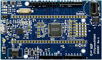
LPCXpresso845MAX
-
Core
Cortex-M0+
-
Device
LPC845M301JBD64 -
CMSIS Pack
LPCXpresso845MAX_BSP
-
usart_terminal
Keil Studio AC6, GCC, IARThis example demonstrate configuration and use of the USART module in interrupt-driven asynchronous mode on communication with a terminal emulator calling the USART transactional APIs. USART will echo back every character to terminal emulator, and send back all received characters once users press [Enter] key.
Download Pack -
usart_terminal
Keil Studio, µVision AC6This example demonstrate configuration and use of the USART module in interrupt-driven asynchronous mode on communication with a terminal emulator calling the USART transactional APIs. USART will echo back every character to terminal emulator, and send back all received characters once users press [Enter] key.
Download Pack -
usart_transfer_dma
Keil Studio, µVision AC6This example shows how to use the DMA driver to implement a double buffer receive scheme from the USART The example shows the double buffer constructed using two descriptors (g_pingpong_desc). These descriptors are cycled from one to the other.Things to note- The descriptors of the ping pong transfer need to be aligned to size 16- The initial transfer will perform the same job as first descriptor of ping pong, so the first linkeage is to go to g_pingpong_desc[1]- g_pingpong_desc[1] then chains the g_pingpong_desc[0] as the next descriptor- The properties are set up such that g_pingpong_desc[0] (and the initial configuration uses INTA to signal back to the callback)- g_pingpong_desc[1] uses INTB to signal to the callback- The scheduled callback uses this information to know which data was last writtenA note on Performance The intent of this example is to illustrate how a double-buffer scheme can be implemented using the dma. The performance of this example will be limited to how quickly the echo printer can read-out the data from the ping pong buffer and display it. This means that the example will work well if characters are entered at a rate where the DMA callback to echo the string can keep up with the input stream. Connecting the USARTRX to a continuous fast speed will cause the DMA to fall behind.
Download Pack -
usart_transfer_dma
Keil Studio AC6, GCC, IARThis example shows how to use the DMA driver to implement a double buffer receive scheme from the USART The example shows the double buffer constructed using two descriptors (g_pingpong_desc). These descriptors are cycled from one to the other.Things to note- The descriptors of the ping pong transfer need to be aligned to size 16- The initial transfer will perform the same job as first descriptor of ping pong, so the first linkeage is to go to g_pingpong_desc[1]- g_pingpong_desc[1] then chains the g_pingpong_desc[0] as the next descriptor- The properties are set up such that g_pingpong_desc[0] (and the initial configuration uses INTA to signal back to the callback)- g_pingpong_desc[1] uses INTB to signal to the callback- The scheduled callback uses this information to know which data was last writtenA note on Performance The intent of this example is to illustrate how a double-buffer scheme can be implemented using the dma. The performance of this example will be limited to how quickly the echo printer can read-out the data from the ping pong buffer and display it. This means that the example will work well if characters are entered at a rate where the DMA callback to echo the string can keep up with the input stream. Connecting the USARTRX to a continuous fast speed will cause the DMA to fall behind.
Download Pack -
usart_transfer_hardware_flow_control
Keil Studio, µVision AC6The usart_transfer_hardware_flow_control example project demonstrates the usage of the hardware flow control function. This example sends data to itself(loopback), and hardware flow control is enabled in the example. The CTS(clear-to-send) pin is for transmiter to check if receiver is ready, if the CTS pin is asserted, transmiter starts to send data. The RTS(request-to-send) pin is for receiver to inform the transmiter if receiver is ready to receive data. So, please connect RTS to CTS pin directly.
Download Pack -
usart_transfer_hardware_flow_control
Keil Studio AC6, GCC, IARThe usart_transfer_hardware_flow_control example project demonstrates the usage of the hardware flow control function. This example sends data to itself(loopback), and hardware flow control is enabled in the example. The CTS(clear-to-send) pin is for transmiter to check if receiver is ready, if the CTS pin is asserted, transmiter starts to send data. The RTS(request-to-send) pin is for receiver to inform the transmiter if receiver is ready to receive data. So, please connect RTS to CTS pin directly.
Download Pack -
usart_transfer_interrupt
Keil Studio, µVision AC6usart_transfer_interrupt
Download Pack -
usart_transfer_interrupt
Keil Studio AC6, GCC, IARusart_transfer_interrupt
Download Pack -
usart_transfer_rb_dma
Keil Studio, µVision AC6This example shows how to use the DMA driver to implement a ring buffer to receive the data, and routine will send back every 8 characters.
Download Pack -
usart_transfer_rb_dma
Keil Studio AC6, GCC, IARThis example shows how to use the DMA driver to implement a ring buffer to receive the data, and routine will send back every 8 characters.
Download Pack