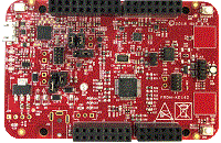
1. Boards
  2. FRDM-KE16Z

FRDM-KE16Z

NXP
FRDM-KE16Z
VSCode with the Arm Keil Studio extension

Accelerate your application development with example projects

Import your chosen project to Keil Studio for VS Code or Keil Studio Cloud, or download for use in Keil uVision.

Learn more about Keil tools
  • Keil Studio AC6, GCC, IAR

    The pdb_adc12_trigger example shows how to use the PDB to generate a ADC trigger.Based on the basic counter, to use the ADC trigger, just to enable the ADC trigger's "milestone" and set the user-defined value for it.After the PDB counter is triggered to start, when the counter pass the "milestone", the ADC's Pre-Trigger would be generated and sentto the ADC12 module.In this example, the ADC12 is configured with hardware trigger and conversion complete interrupt enabled.Once it gets the trigger from the PDB, the conversion goes, then the ISR would be executed.

    Download Pack
  • Keil Studio, µVision AC6

    The pdb_delay_interrupt example show how to use the PDB as a general programmable interrupt timer.The PDB is triggered by software, and other external triggers are generated from PDB in this project,so that user can see just a general counter is working with interrupt.

    Download Pack
  • Keil Studio AC6, GCC, IAR

    The pdb_delay_interrupt example show how to use the PDB as a general programmable interrupt timer.The PDB is triggered by software, and other external triggers are generated from PDB in this project,so that user can see just a general counter is working with interrupt.

    Download Pack
  • Keil Studio, µVision AC6

    The pflash example shows how to use flash driver to operate program flash:

    Download Pack
  • Keil Studio AC6, GCC, IAR

    The pflash example shows how to use flash driver to operate program flash:

    Download Pack
  • Keil Studio, µVision AC6

    The Power manager demo application demonstrates the use of power modes in the KSDK. The demo use the notification mechanismand prints the power mode menu through the debug console, where the user can set the MCU to a specific power mode. The usercan also set the wakeup source by following the debug console prompts. The purpose of this demo is to demonstrate theimplementation of a power mode manager. The callback can be registered to the framework. If a power mode transition happens,the callback will be called and user can do something. Tips: This demo is to show how the various power mode can switch to each other. However, in actual low power use case, to save energy and reduce the consumption even more, many things can be done including: - Disable the clock for unnecessary module during low power mode. That means, programmer can disable the clocks before entering the low power mode and re-enable them after exiting the low power mode when necessary. - Disable the function for unnecessary part of a module when other part would keep working in low power mode. At the most time, more powerful function means more power consumption. For example, disable the digital function for the unnecessary pin mux, and so on. - Set the proper pin state (direction and logic level) according to the actual application hardware. Otherwise, the pin cirrent would be activied unexpectedly waste some energy. - Other low power consideration based on the actual application hardware.

    Download Pack
  • Keil Studio AC6, GCC, IAR

    The Power mode switch demo application demonstrates the use of power modes in the KSDK. The demo prints the power mode menuthrough the debug console, where the user can set the MCU to a specific power mode. The user can also set the wakeupsource by following the debug console prompts. The purpose of this demo is to show how to switch between different power modes, and how to configure a wakeup source and wakeup the MCU from low power modes. Tips: This demo is to show how the various power mode can switch to each other. However, in actual low power use case, to save energy and reduce the consumption even more, many things can be done including: - Disable the clock for unnecessary module during low power mode. That means, programmer can disable the clocks before entering the low power mode and re-enable them after exiting the low power mode when necessary. - Disable the function for unnecessary part of a module when other part would keep working in low power mode. At the most time, more powerful function means more power consumption. For example, disable the digital function for the unnecessary pin mux, and so on. - Set the proper pin state (direction and logic level) according to the actual application hardware. Otherwise, the pin cirrent would be activied unexpectedly waste some energy. - Other low power consideration based on the actual application hardware. - Debug pins(e.g SWD_DIO) would consume addtional power, had better to disable related pins or disconnect them.

    Download Pack
  • Keil Studio, µVision AC6

    The Power mode switch demo application demonstrates the use of power modes in the KSDK. The demo prints the power mode menuthrough the debug console, where the user can set the MCU to a specific power mode. The user can also set the wakeupsource by following the debug console prompts. The purpose of this demo is to show how to switch between different power modes, and how to configure a wakeup source and wakeup the MCU from low power modes. Tips: This demo is to show how the various power mode can switch to each other. However, in actual low power use case, to save energy and reduce the consumption even more, many things can be done including: - Disable the clock for unnecessary module during low power mode. That means, programmer can disable the clocks before entering the low power mode and re-enable them after exiting the low power mode when necessary. - Disable the function for unnecessary part of a module when other part would keep working in low power mode. At the most time, more powerful function means more power consumption. For example, disable the digital function for the unnecessary pin mux, and so on. - Set the proper pin state (direction and logic level) according to the actual application hardware. Otherwise, the pin cirrent would be activied unexpectedly waste some energy. - Other low power consideration based on the actual application hardware. - Debug pins(e.g SWD_DIO) would consume addtional power, had better to disable related pins or disconnect them.

    Download Pack